
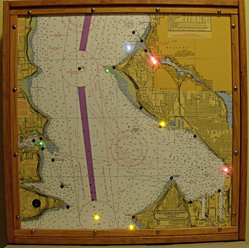
Aids to Navigation demonstration chart of Elliot Bay and Seattle, the Aids to Navigation are demonstrated using flashing LED’s. The lights flash with the same characteristic as the lights on the water.
This is an Aids To Navigation (ATON) display demonstration board I made, there are flashing LED’s to demonstrate selected ATON’s in the Elliot Bay area around Seattle Washington.
There are 27 Aids represented from just south of the Alki Lighthouse to the Shilshole Marina. The chart is about 24 inches square.
I used a Basic Stamp II from Parallax to drive a selection of LED’s to demonstrate selected Aids to Navigation.
Why did I use a Basic Stamp II which has been around for several years and not the latest fancy computer? I had the Basic Stamp left over from many years ago when I was going to teach myself how to program small microcomputers. The BS II only has 16 output lines and I at first did not think it would work for this project, a few emails with the Tech folks at Parallax and they explained about the 74HC595 Serial to Parallel Shift Register to expand the number of outputs. At that point I was sort of off and running working on the code and the design and getting LED’s to blink.
I wanted the lights to blink with the same characteristics as those on the water to make the display as realistic as possible. A bit of an internet search led me to the IALA (International Association of Lighthouse Authorities) now the International Association of Marine Aids to Navigation and Lighthouse Authorities and their publication “Rhythmic Characters of Lights on Aids to Navigation” which covered the time on and time off for different light patterns..
The program is fairly simple (after 19 or so revisions and simplifications), a series of IF statements to turn a light on and off at specific intervals. The BS II does not have any clock or timers in it so the program scan was adjusted to 0.10 sec as a simplified time base. Since there is no user input the slow scan time is not an issue.
The BS II has a very limited data table for variables I found out, which limited the number of individual counters for the lights. I wanted to use individual counters for each light, once I got the program running I changed the start values for the counters so the lights did not start all at the same time, this gives a bit more realistic view than having all the 4 seconds lights flash on and off at the same time for example.
For outputs I started with the 74HC595 chip, but found out that the LED’s I needed to use would fry the chip if too many were turned on at the same time, that was when the UNL2803A Darlington Array chips were added. Later I found another Serial to Parallel Shift Register chip I could have used that has more current carrying ability, so next time I will probably use a different chip set to make things simpler.
The current draw for the colored lights was adjusted to about 18ma with a dropping resistor, it was a bit of a trial and error thing but that drives the LED’s bright enough to be seen outside and from across a room. My rough calculations indicate the display should run a full day on the five rechargeable AA batteries.
Diffused LED’s seem to work the best, some of the LED’s are not diffused and some fine Scotch-Bright rubbed on the end of the LED worked to diffuse the white and Red/White bulbs.
The video of the Chart and LED’s in action is only 26 seconds long. One light does not have the proper characteristics, can you spot it? I made a programming error and one person suggested leaving the error in as a test.
General construction notes and such:
The frame was made of decent looking wood, cut to size by the lumber yard then stained before assembling. 3/4 x 3/4 x 1/16 inch aluminum angle was mounted inside the frame with 10-32 stainless machine screws and placed to have the chart recessed a bit to protect it and the back side was designed to allow a back of 1/4 inch Plexiglass to protect the wiring with space on the outside for a battery pack.
The chart is mounted on a 23 1/2 in square piece of 1/16 inch thick sheet of aluminum with lots of permanent double sided sticky tape. I made a center-punch mark for each of the LED’s (don’t strike the punch too hard, you can put a large dent in the aluminum. I drilled 1/4 inch holes to mount the LED’s then stuck to chart to the aluminum and cut the holes in the chart to match the holes in the aluminum sheet, be very careful. The chart was printed on 24 inch wide paper then laminated to protect the printing. I trimmed the chart to match the aluminum sheet.
The aluminum sheet is structural to keep the frame square, I squared the frame then drilled the holes to hold the trim piece around the outside of the chart. I used a piece of flat bar aluminum with a hole drilled in it the same size as the drill bit I was using as a guide when drilling the holes to reduce the chance of tearing the wood and to keep the holes spaced evenly to help the looks.
The wiring was done on a large prototype board, the board was mounted to the aluminum sheet using Weld-Mount studs, an adhesive system the saved me trying to drill or fasten to the aluminum sheet with any type of threaded fastener.
Yes for those engineers out there that checked the board wiring with the BS II, there is no communication link set up, I programmed the BS II in a teaching carrier then transferred the chip to this board, be careful you don’t bend the legs if you do this. At some point in the future I plan on wiring the DB9 connector to allow the chip to be programmed on this board.
I also plan to add an extension power lead so the display board can be powered with a DC power supply that plugs into the wall.
The bottom of the display has rubber cushion pads to prevent marring anything it is set on and prevent it from sliding around.
If you would like to see the chart display in action, look for it at selected Coast Guard Auxiliary public events and classes in the Seattle area, some of our PA staff hope to have it at the Seattle Boat Show in January so stop by the booth and say hello. This also might be on display at the Alki Lighthouse for tours during the summer if we can find a place to mount it.
Partial Parts List
The parts list is provided as a courtesy, I have no financial interest in any of the companies nor do I receive any remuneration for the parts, the link is provided solely to make it easier for the readers to see some of the parts I used.
Parallax Basic Stamp II
5mm Red LED – Sparkfun
5mm Green LED – Sparkfun
5mm Yellow LED – Sparkfun
5mm Red / White LED Common Anode – Unique-Leds
5mm White ??
LED Mounts / Holders ?? Simple black snap in
74HC595 Serial to Parallel Shift Register – Parallax
UNL2803A Darlington Array – Parallax
Supporting Documents
Program Listing (PDF)
Electrical Drawings (PDF)
Light List and timing (PDF)
Nautical Chart – Elliot Bay and Shilshole (PDF)
If you have further questions or feedback about the project please leave them in the comments and I will try and answer them, this might help others that might have the same question.
General Disclaimer and Caution: All files are provided as is with no guarantee I have done my best to not leave something out, but the information is not intended to be a full set of instructions to duplicate what I have done, I may have made an error in the documentation or failed to show a change made in final assembly and wiring. If you are not experienced working with this type of design I recommend that you get assistance and you want to double check everything to prevent errors or damage to any equipment or yourself.
I would also like to thank Michael Colyar and Mike Sinclair and several others for help with this, providing feedback and suggestions that helped made the project a success.
-

- Aids to Navigation demonstration chart of Elliot Bay and Seattle, the Aids to Navigation are demonstrated using flashing LED’s. The lights flash with the same characteristic as the lights on the water.
-

- Rear view showing construction and wiring details for Aids to Navigation demonstration chart of Elliot Bay and Seattle, the Aids to Navigation
-

- Board wiring for Aids to Navigation demonstration chart of Elliot Bay and Seattle, the Aids to Navigation are demonstrated using flashing LED’s.
– c / m –


Very nice Mike.
Thanks
I think this display will be highly effective at helping students understand chart information.
Thanks – I hope it will help people to understand the markings better –
What a wonderful project you have done! I would like to do one for the Bellingham area; my arduino is just sittin’ around and I suppose I can use that (if I find out on Sparkfun or LadyAda how to drive that many lights). Did you say, what are you going to do with your display? Thanks much, I’ll go read your documents next….
There is code in the Sparkfun Tutorial to drive the 74HC595 (and probably the Arduino tutorial section since many of the tutorials seem to come from them in some form or another) – – Take a look at ( Shift Register 8-Bit High-Power – TPIC6B595 ) uses the same program but the pins are a bit different – that should be able to be used in place of the 74HC595 and drive 8 LED’s at 20 ma sinking current – that will reduce the chip count by almost half and make the wiring much easier
What it will be used for is still a work in progress, but public events to get visitors to stop, we hope the Alki Lighthouse for tour days, demo in public ed classes and as an attention getter at the CG Aux booth at the Seattle Boat show and anything else we can think of – everyone likes it and is impressed.
Let me know if you have more questions, be glad to try and help
Thanks for stopping by and let me know how the project goes
Thanks much for this; what a wonderful project. I have an arduino sittin’ around with nothing to do… So where can the display be seen? You, and your blog, rock!
Glad you like my site
See the comment above for some places I hope to have the display out for all to see